
9.6 KiB
Multi-Functional Controller (MFC)






A custom, high-performance handheld remote controller engineered from scratch for dual-role applications: long-range, low-latency RC vehicle control and USB/Bluetooth HID gaming.
Built around the ESP32-S3 (Xtensa® 32-bit LX7 dual-core @ 240 MHz), this project bridges hardware and software engineering—combining magnetic Hall-effect sensing, RF telemetry, hardware pulse-counted rotary inputs, hardware PWM audio synthesis, and an SPI graphics pipeline into a unified, battery-powered embedded platform.
Prototype Showcase
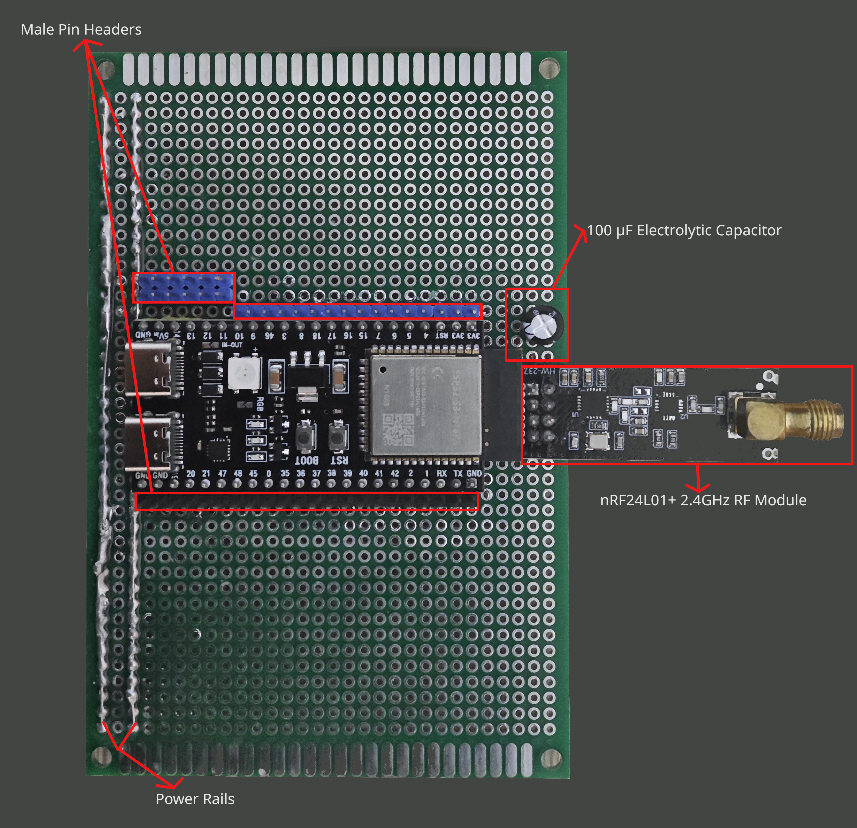
Figure 1: Top assembly layout — Dual Hall-effect joysticks, rotary encoder, tactile buttons, 1.3" SPI OLED display, NeoPixel telemetry bar, and audio transducers.
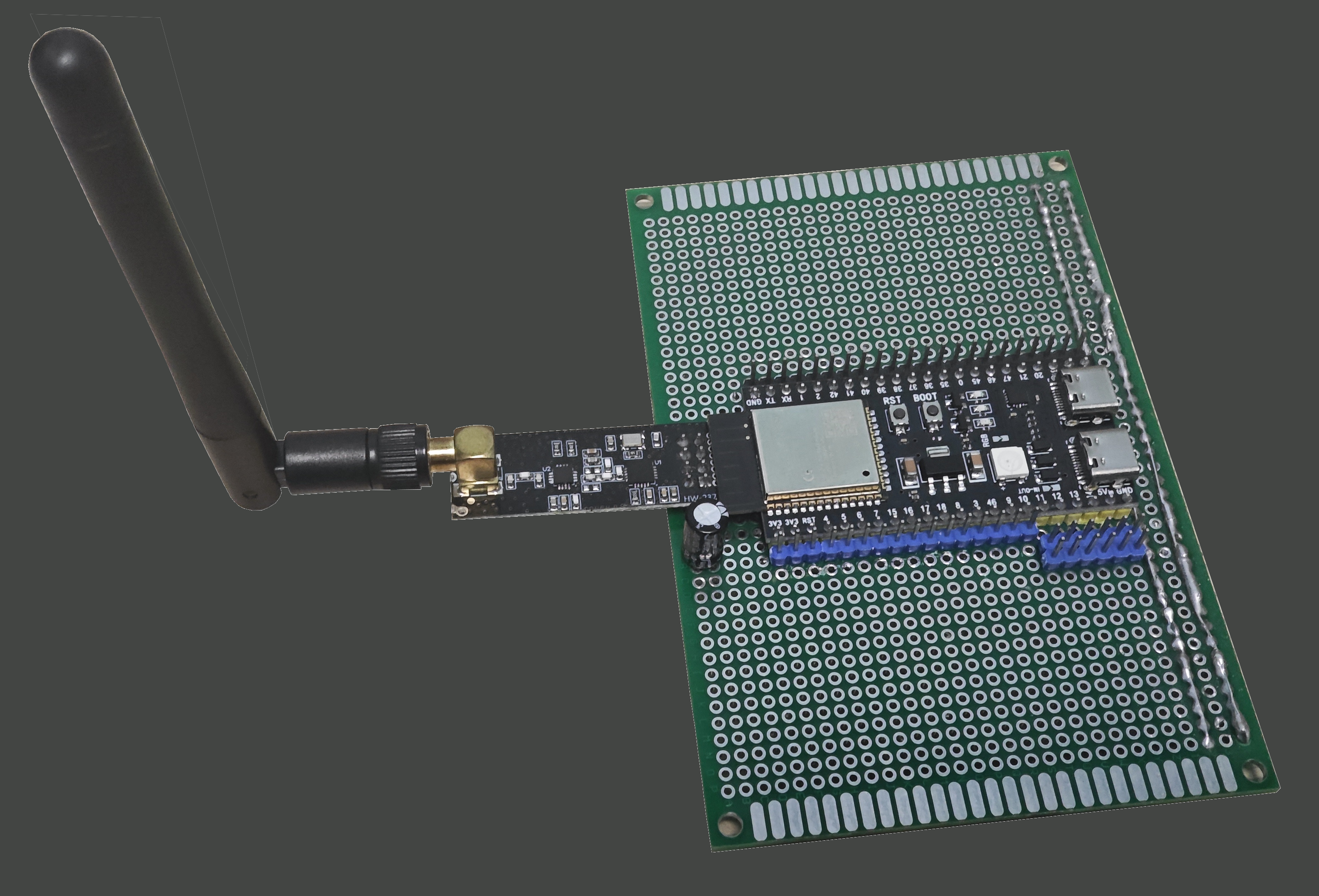
Figure 2: Ergonomic profile — 2.4 GHz high-gain dipole antenna connected to the NRF24L01+ RF transceiver, rotary dial, and dual USB-C ports.
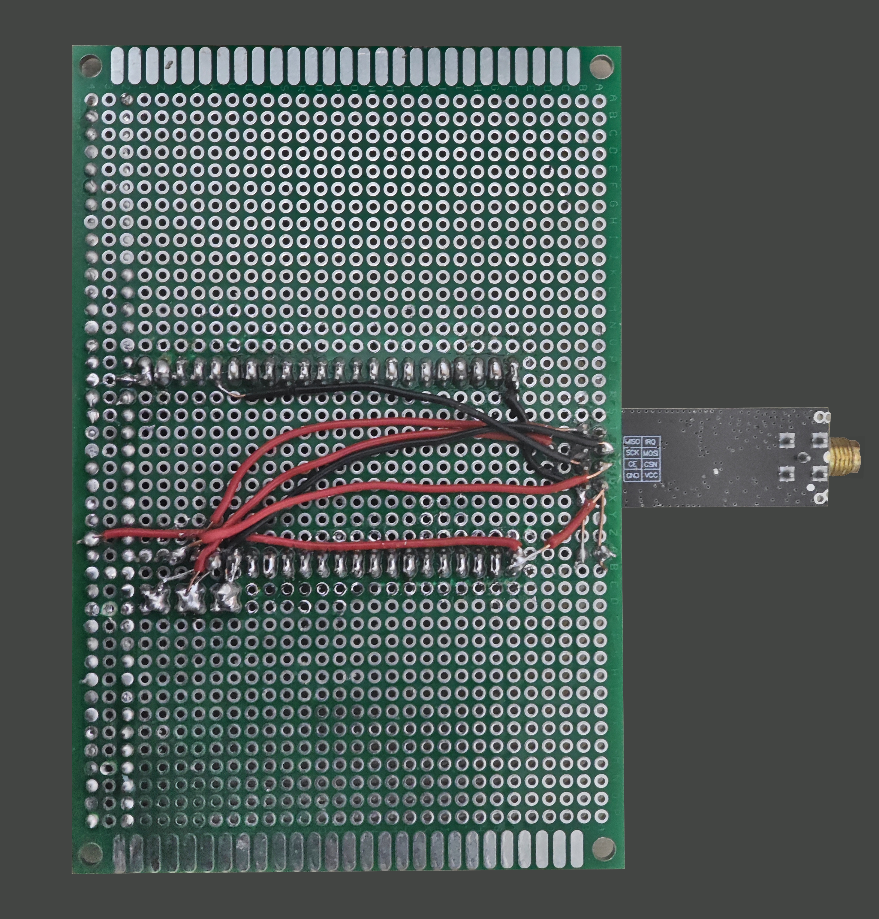
Figure 3: Underbody point-to-point bus routing — 6×9 cm perfboard with dedicated decoupled power rails (100 µF smoothing capacitor) and direct GPIO signal lines.
Key Hardware & Architectural Features
- Microcontroller Core: Espressif ESP32-S3-N16R8 (16 MB Quad SPI Flash, 8 MB Octal PSRAM) running FreeRTOS preemptive multitasking.
- Dual Wireless Pipelines:
- 2.4 GHz RF (NRF24L01+): Dedicated SPI radio module with external SMA antenna for low-latency, deterministic RC telemetry.
- Bluetooth 5.0 LE & Wi-Fi: Native wireless stacks for PC/gamepad HID modes and wireless telemetry streaming.
- Precision Analog & Digital Controls:
- Dual Hall-Effect Joysticks: Contactless magnetic sensing for zero stick drift and extended durability.
- Hardware Pulse-Counted Rotary Encoder: Quadrature decoding handled in hardware via the ESP32-S3
pulse_cntperipheral to guarantee zero missed ticks during high-load processing loops. - Dedicated Navigation Buttons: Tactile push-buttons configured with internal pull-ups for UI interaction and control toggling.
- Multi-Sensor Audio & Visual Telemetry:
- 1.3" SPI OLED Display (SH1106 / SSD1306): Driven via hardware DMA SPI (
SPI2_HOST) with custom frame buffering for menus, telemetry, and live status readouts. - Polyphonic Melodic Synthesis: Passive buzzer modulated via hardware LEDC PWM timer (
LEDC_TIMER_0, 13-bit duty resolution). - Percussive Acoustic Alerts: Dual active buzzers for instant tactile/auditory feedback and warning signals.
- Visual Beat & Metric Indicators: Dedicated Kick (GPIO 21) and Hi-Hat (GPIO 22) LEDs alongside an 8-LED WS2812B NeoPixel RGB strip driven via RMT.
- 1.3" SPI OLED Display (SH1106 / SSD1306): Driven via hardware DMA SPI (
- Power Subsystem:
- Dual parallel 18650 Li-ion cells delivering 4800 mAh combined capacity.
- Dual USB-C ports: one dedicated for high-efficiency battery charging and one for USB-UART flashing, debugging, and wired HID gamepad control.
- 100 µF low-ESR electrolytic capacitor buffering transient current spikes from RF transmission bursts and buzzer pulses.
GPIO Pinout & Peripheral Mapping
The firmware (firmware/main/mmcontroller.c) allocates hardware peripherals across the ESP32-S3 as follows:
| Peripheral / Signal | GPIO | Mode / Hardware Interface | Description |
|---|---|---|---|
| Rotary Encoder CLK | GPIO 32 |
ESP-IDF pulse_cnt Unit |
Quadrature channel A (hardware edge counter) |
| Rotary Encoder DT | GPIO 33 |
ESP-IDF pulse_cnt Unit |
Quadrature channel B (direction sensing) |
| Rotary Push Switch | GPIO 16 |
Digital Input (PULLUP) |
Rotary push-button (mode / parameter select) |
| Button: Pause / Play | GPIO 13 |
Digital Input (PULLUP) |
Navigation / transport control |
| Button: Next / Forward | GPIO 14 |
Digital Input (PULLUP) |
Navigation / channel advance |
| Passive Buzzer | GPIO 25 |
LEDC PWM (LEDC_CHANNEL_0) |
Hardware PWM audio synthesis (frequency & melody) |
| Active Buzzer 1 | GPIO 26 |
Digital Output | Percussive acoustic click / telemetry alert 1 |
| Active Buzzer 2 | GPIO 27 |
Digital Output | Percussive acoustic click / telemetry alert 2 |
| LED: Kick Trigger | GPIO 21 |
Digital Output | Visual beat / primary telemetry indicator |
| LED: Hat Trigger | GPIO 22 |
Digital Output | Visual beat / secondary telemetry indicator |
| OLED Data/Command (DC) | GPIO 2 |
Digital Output | 1.3" OLED command vs data selection |
| OLED Reset (RES) | GPIO 4 |
Digital Output | Hardware display reset line |
| OLED Chip Select (CS) | GPIO 5 |
SPI Device Select (SPI2) |
Display SPI bus enable |
| OLED Clock (CLK) | GPIO 18 |
SPI Master Clock (SPI2) |
Hardware SPI clock line (DMA enabled) |
| OLED MOSI | GPIO 23 |
SPI Master Output (SPI2) |
Hardware SPI data out line (DMA enabled) |
| NeoPixel RGB Bar | Config | RMT Peripheral | WS2812B 8-pixel addressable RGB telemetry strip |
Repository Structure
multi-functional-controller/
├── firmware/                        # ESP-IDF C99/C++ Firmware Project
│   ├── CMakeLists.txt               # Top-level CMake project configuration
│   ├── sdkconfig                    # ESP32-S3 configuration (PSRAM, Flash, FreeRTOS)
│   └── main/
│       ├── CMakeLists.txt           # Component registration
│       ├── idf_component.yml        # Espressif component dependencies (led_strip)
│       └── mmcontroller.c           # Core firmware: FreeRTOS tasks, pulse counter, SPI OLED, LEDC PWM
├── hardware/                        # KiCad 10 Electronic Design Automation (EDA)
│   ├── mfc-1.kicad_pro              # KiCad project file
│   ├── mfc-1.kicad_sch              # Complete schematic design & component symbols
│   └── mfc-1.kicad_pcb              # Board layout & routing rules
├── images/                          # High-resolution prototype photography
│   ├── TOP_VIEW.png                 # Front control surface overview
│   ├── SIDE_VIEW_WITH_ANTENNA.png   # RF antenna and profile perspective
│   └── BOTTOM_VIEW.png              # Perfboard underside bus wiring
├── .gitignore                       # Clean repository filter (builds, caches, local configs)
└── README.md                        # Master engineering documentation
Getting Started: Building the Firmware
Prerequisites
- ESP-IDF v5.1+ installed and exported into your environment:
. $HOME/esp/esp-idf/export.sh
Build & Flash
-
Navigate to the firmware directory:
cd firmware -
Set target to ESP32-S3:
idf.py set-target esp32s3 -
Compile the firmware:
idf.py build -
Flash to the controller and open serial monitoring:
idf.py -p /dev/ttyUSB0 flash monitor(Replace
/dev/ttyUSB0with your serial device node, e.g./dev/ttyACM0).
Hardware CAD & Schematic Editing
The electronic schematic is developed in KiCad 10:
- Open the project:
kicad hardware/mfc-1.kicad_pro - Inspect or modify the schematic in
eeschema(hardware/mfc-1.kicad_sch). - To generate vector schematics for documentation or web publication:
- Select File
\rightarrowPlot\rightarrowSVG or PDF.
- Select File
Roadmap & Milestones
- Initial hardware breadboard and perfboard prototype (6×9 cm assembly).
- Dual-core ESP-IDF firmware setup with FreeRTOS task scheduling.
- Hardware pulse-counter integration for quadrature rotary encoder (
driver/pulse_cnt.h). - Hardware LEDC PWM audio synthesis & percussive buzzer drivers.
- High-speed SPI OLED graphics driver with DMA channel support.
- Addressable WS2812B NeoPixel telemetry integration.
- Custom multi-layer printed circuit board (PCB) design in KiCad.
- 3D-printable ergonomic handheld enclosure (PETG / Resin).
- Low-latency NRF24L01+ bidirectional packet protocol with ACK-payload telemetry.
- Standard USB Gamepad HID descriptor integration for plug-and-play PC gaming.
Author & Project Notebook
- Author: Ertunç Özbay
- Personal Workshop & Portfolio: ertuncozbay.dev
- Project Detail Page: ertuncozbay.dev/projects/multi-functional-controller.html
- License: MIT License