
17 KiB
Multi-Functional Controller (MFC) & 4WD RC Vehicle






1. Project Overview & Aim
- Primary Goal: Engineer a high-performance, bare-metal handheld remote controller (MFC) from scratch using an ESP32-S3-N16R8, paired with a custom 4WD RC Vehicle controlled by an ARM Cortex-M3 (
GD32F103C8T6). - Secondary Objectives: Extend the controller's capabilities to include a cloud-connected AI voice assistant (
MAX4466), local FAT32 SD card telemetry logging, and PC Gamepad (USB HID / Bluetooth) support. - Tech Stack: C/C++, ESP-IDF v5.x (FreeRTOS), bare-metal register manipulation, SPI, I2C, Hardware Pulse Counter (
PCNT), and One-ShotADC1.
2. Current Situation & Early Prototype Showcase (Rev 0.1)
Note
Early Prototype Notice (Rev 0.1 Carrier Build):
The photographs and schematic below represent the very early initial stage of the physical hardware build. At this stage, only the core carrier foundation is soldered onto the 6×9 cm perfboard: the ESP32-S3-N16R8 microcontroller, nRF24L01+ 2.4 GHz radio module, 100 µF electrolytic burst-smoothing capacitor, signal male pin headers, and power rail male headers.
The repository's firmware (firmware/main/mmcontroller.c) and schematic (hardware/mfc-1.kicad_sch) are intentionally kept matched to this verified Rev 0.1 hardware baseline. As the new modules (1.8" ST7789 TFT,K-Silver PS5 Hall-Effect Joysticks,MicroSD,MAX4466,2N2222buzzer stage, and enclosure) are physically integrated, both the hardware photos and firmware will be updated step-by-step.
- Controller Prototype (Rev 0.1): Prototyped on a 6×9 cm perfboard. The
ESP32-S3-N16R8communicates over a sharedSPI2_HOSTbus with a NordicnRF24L01+2.4 GHz transceiver and a temporary benchtop 1.3" SH1106 OLED display connected via the male breakout headers. - Current Baseline Firmware: A deterministic FreeRTOS state machine (
firmware/main/mmcontroller.c) handles hardware quadrature decoding (PCNT) for aKY-040rotary encoder menu UI,300 mssoftware button debouncing, and live 2.4 GHz RF channel configuration (0–125). - Display Hardware Pivot (
1.3" OLED\rightarrow1.8" ST7789 TFT): Bench testing revealed that the 7-pin 1.3" OLED module lacks a physical Chip Select (CS) pin (hard-tied to GND internally), causing SPI bus collisions when sharing the bus. We are upgrading to a 1.8" ST7789 Color TFT LCD (which exposes a dedicated hardwareCSpin onGPIO 10) to share the SPI bus safely without bus contention. - Manufacturing & Enclosure Status: Paused cutting the rigid ABS plastic project box (
DT-100,190 × 137 × 59 mm) until next month when a variable 3-speed rotary tool (Dremel/E108) and2.35 mmdiamond cutting wheels arrive to ensure clean, professional cutouts without melting the ABS plastic.
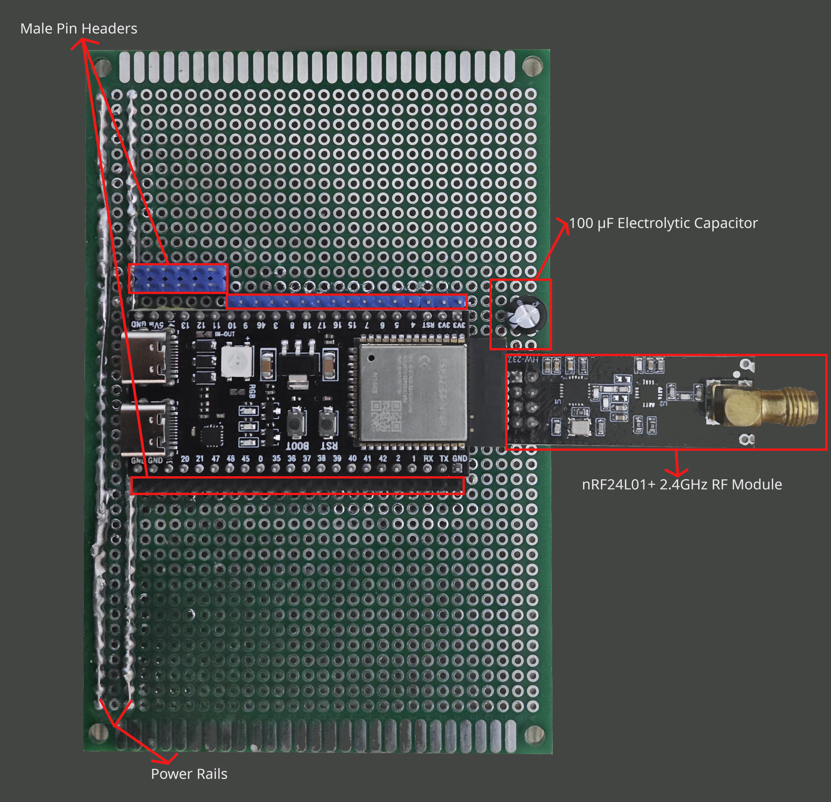
Figure 1 (Early Build — Rev 0.1): Initial 6×9 cm perfboard carrier top view — ESP32-S3-N16R8 module, nRF24L01+ 2.4 GHz transceiver, 100 µF decoupling capacitor, peripheral male pin headers, and power rail male headers. (Will be updated as Phase 2 modules are installed).
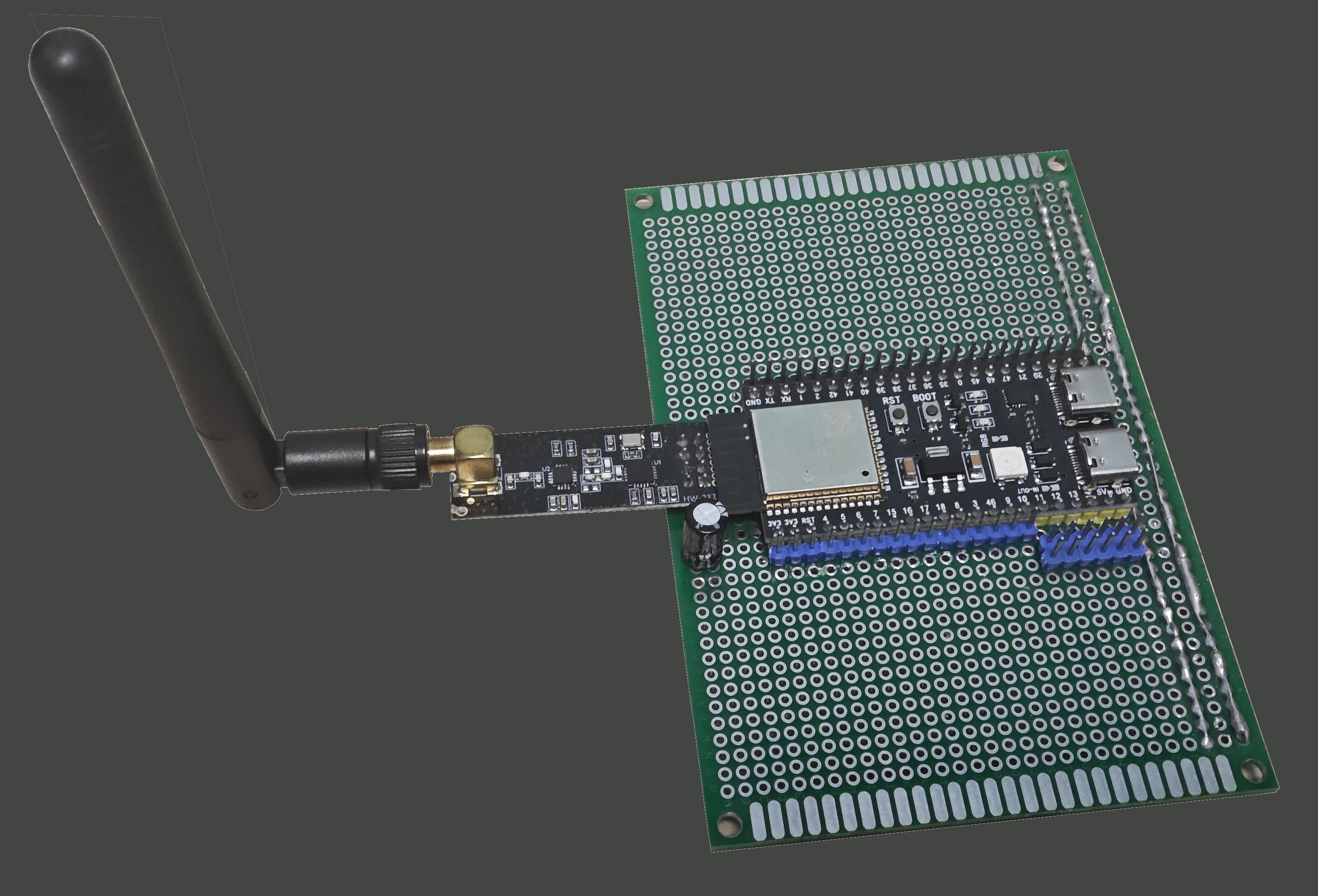
Figure 2 (Early Build — Rev 0.1): Side profile showing the external 2.4 GHz SMA dipole antenna connected to the nRF24L01+ transceiver and dual USB-C ports (Native USB-OTG & UART).
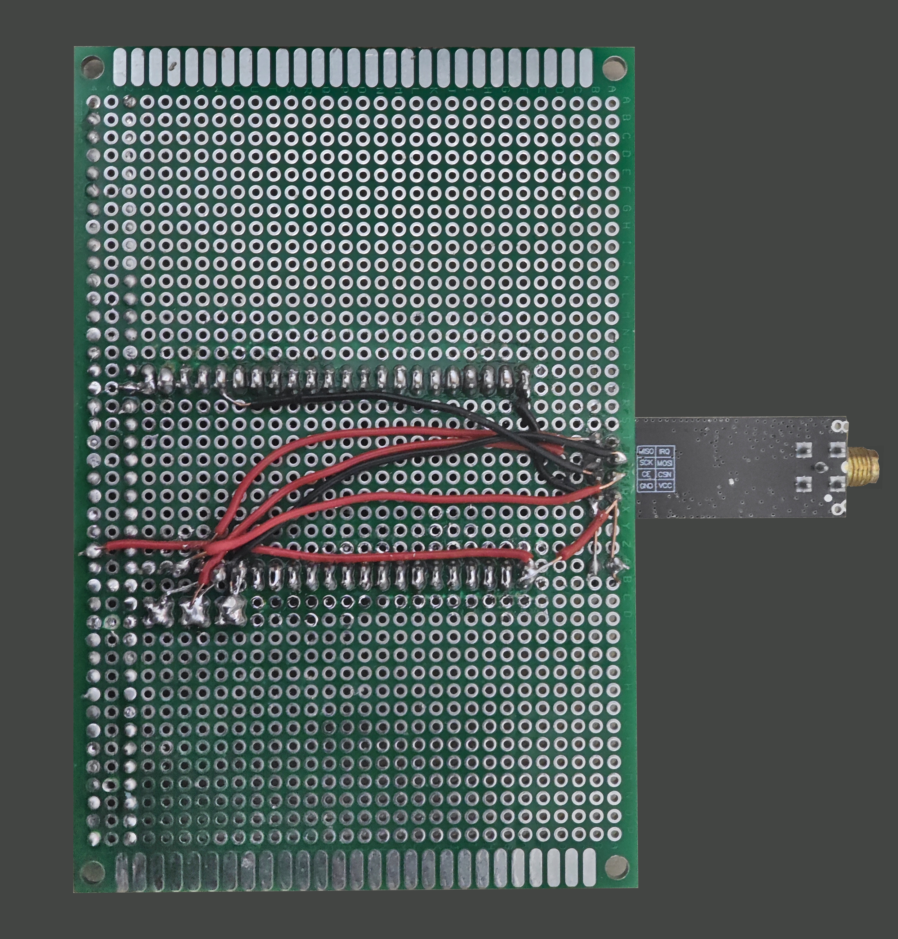
Figure 3 (Early Build — Rev 0.1): Underbody point-to-point solder bridges, common ground/power rails, and shared SPI2 signal routing on the 6×9 cm perfboard.
Rev 0.1 Core Carrier Schematic (hardware/mfc-1.kicad_sch)
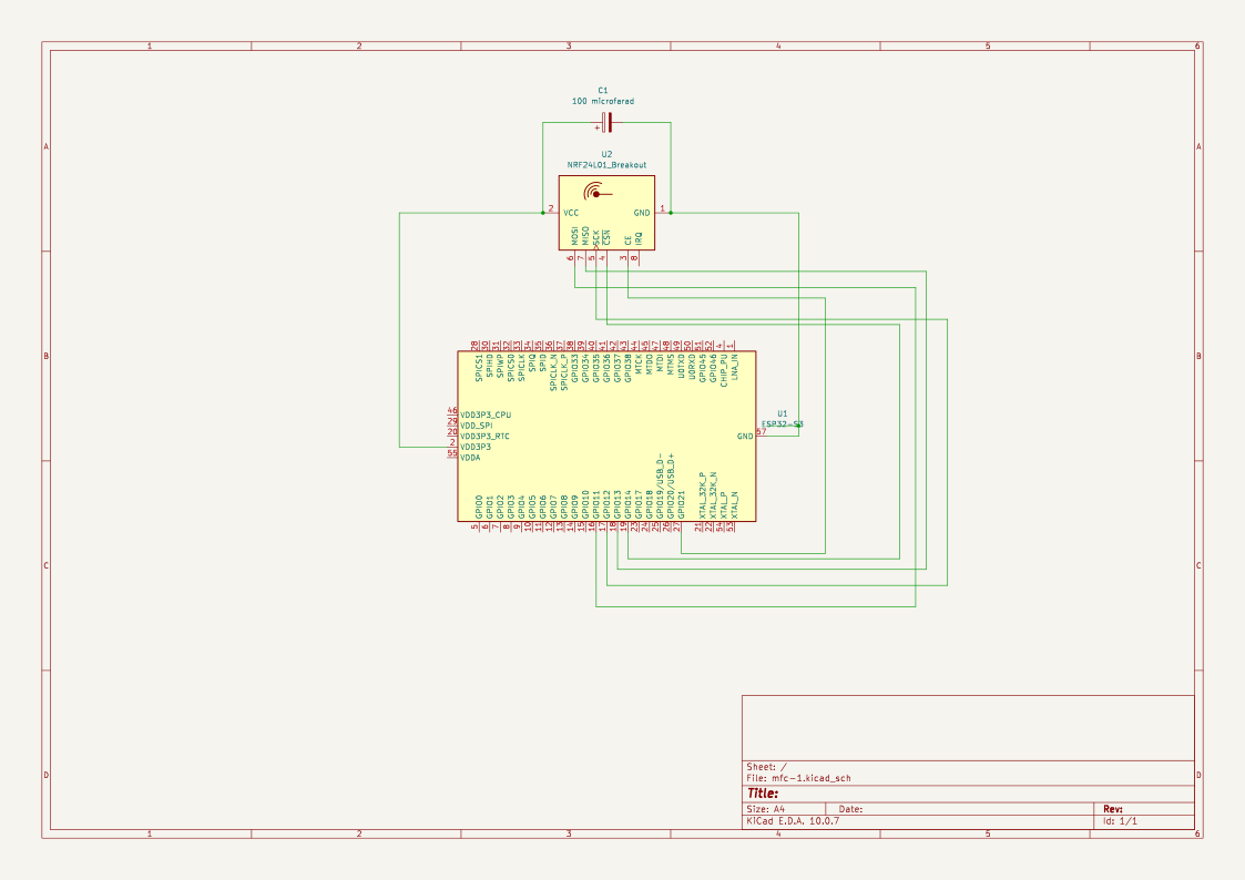
Figure 4: KiCad 10 schematic of the Rev 0.1 Core Carrier (`U1: ESP32-S3`, `U2: nRF24L01+`, `C1: 100 µF` decoupling capacitor).
3. Dual-Node System Architecture & Bill of Materials (BOM)
flowchart LR
subgraph TX["Node 1: Handheld Controller (ESP32-S3-N16R8)"]
MCU["ESP32-S3-N16R8<br/>(FreeRTOS Dual-Core)"]
HALL["2x K-Silver PS5<br/>Hall-Effect Joysticks"] -->|ADC1| MCU
MIC["MAX4466 Electret<br/>Mic Pre-Amp"] -->|ADC1| MCU
ENC["KY-040 Rotary Encoder"] -->|Hardware PCNT| MCU
MCU -->|SPI2_HOST + CS GPIO10| TFT["1.8" ST7789 Color TFT"]
MCU -->|SPI2_HOST + CS| SD["MicroSD Card (FAT32)"]
MCU -->|2N2222 NPN Drivers| BUZ["1x Passive + 2x Active Buzzers"]
MCU -->|SPI2_HOST + CSN GPIO14| NRF_TX["nRF24L01+ 2.4GHz TX"]
end
subgraph RX["Node 2: 4WD RC Vehicle (GD32F103C8T6)"]
NRF_RX["nRF24L01+ PA+LNA<br/>(1km SMA Antenna)"] -->|SPI| GD32["GD32F103C8T6<br/>(ARM Cortex-M3)"]
IMU["MPU9250 9-DOF IMU"] -->|I2C| GD32
TOF["VL53L0X ToF / HC-SR04"] -->|I2C / Divider| GD32
GD32 -->|Closed-Loop PID PWM| MOT["4x JGB37-520 12V<br/>333RPM Encoder Motors"]
end
NRF_TX <==>|"2.4 GHz RF Link (Ch 0-125)"| NRF_RX
3.1 Handheld Controller (MFC — Transmitter Node)
| Subsystem | Component | Technical Details & Role | Build State |
|---|---|---|---|
| MCU | Espressif ESP32-S3-N16R8 | Dual-core Xtensa® LX7 @ 240 MHz, 16 MB Quad SPI Flash, 8 MB Octal PSRAM. | Installed (Rev 0.1) |
| RF Telemetry | Nordic nRF24L01+ Module | 2.4 GHz ISM band transceiver over shared SPI2_HOST. |
Installed (Rev 0.1) |
| Bulk Decoupling | 100 µF Electrolytic + Male Headers | Suppresses nRF24 PTX current spikes; modular header rails for peripherals. | Installed (Rev 0.1) |
| Display | 1.8" ST7789 TFT Color LCD | 3.3V logic, full-color SPI display with dedicated CS pin (replacing 7-pin CS-less 1.3" bench OLED). |
Next Upgrade |
| Joysticks | 2× K-Silver (KS) PS5 Hall-Effect Modules | 3.3V active magnetic contactless gimbals for zero stick drift. | Next Upgrade |
| UI Input | KY-040 Rotary Encoder | Quadrature encoder (CLK, DT, SW) decoded in hardware via ESP32-S3 PCNT. |
Bench Verified |
| Voice AI | MAX4466 Electret Microphone Module | Analog pre-amplifier with adjustable gain for cloud-connected AI voice assistant input. | Next Upgrade |
| Data Logging | Arduino Micro SD Card Module | SPI interface, formatted FAT32 for local telemetry and configuration logging. |
Next Upgrade |
| Audio Output | 1× Passive Buzzer + 2× Active Buzzers | Passive buzzer for melodies + 2× active buzzers for percussive UI clicks, driven by 2N2222 NPN Transistors. | Next Upgrade |
| Power System | Dual 18650 Li-ion + TP4056 + MT3608 | Dual 18650 cells, TP4056 charger, MT3608 DC-DC boost converter (5V rail), 1N5817 Schottky & 1N4001 diodes, 100 nF ceramic caps. |
Next Upgrade |
3.2 RC Vehicle (Receiver Node)
| Subsystem | Component | Technical Details & Role |
|---|---|---|
| MCU | GD32F103C8T6 Mini Board | 32-bit ARM® Cortex®-M3 real-time vehicle controller. |
| RF Telemetry | nRF24L01+ PA+LNA Module | High-power 2.4 GHz transceiver with Power Amplifier, Low-Noise Amplifier, and external SMA antenna (~1 km range). |
| IMU / Navigation | MPU9250 9-DOF Sensor | 3-axis Gyroscope, 3-axis Accelerometer, and 3-axis Magnetometer (I2C) for tilt-compensated heading. |
| Drivetrain | 4× JGB37-520 12V 333 RPM Gear Motors | High-torque 12V DC gear motors with built-in quadrature encoders for closed-loop PID velocity control. |
| Chassis / Box | DT-100 Project Box | Rigid black ABS enclosure (190 × 137 × 59 mm). |
| Power System | 12V Battery + Motor Drivers | 12V traction battery pack, heavy-duty H-bridge motor drivers, and 12–24V Waterproof Main Switch. |
4. Pinout Definitions (ESP32-S3 Controller)
4.1 Current Verified Pin Allocation (firmware/main/mmcontroller.c)
| Bus / Peripheral | Signal | ESP32-S3 Pin | Interface / Mode | Notes |
|---|---|---|---|---|
SPI Hub (SPI2_HOST) |
MOSI |
GPIO 11 |
SPI Master Output | Shared data line (nRF24L01+, Display SDA, MicroSD) |
SPI Hub (SPI2_HOST) |
MISO |
GPIO 13 |
SPI Master Input | Shared data input (nRF24L01+, MicroSD) |
SPI Hub (SPI2_HOST) |
SCK |
GPIO 12 |
SPI Master Clock | Shared clock line (nRF24L01+, Display CLK, MicroSD) |
| nRF24L01+ Radio | CSN |
GPIO 14 |
SPI Chip Select | Dedicated radio bus enable |
| nRF24L01+ Radio | CE |
GPIO 21 |
Digital Output | Radio TX/RX power state activation |
| TFT Display (1.8" ST7789) | CS |
GPIO 10 |
SPI Chip Select | Dedicated display bus enable |
| TFT Display (1.8" ST7789) | DC |
GPIO 9 |
Digital Output | Command vs. frame data selection |
| TFT Display (1.8" ST7789) | RES |
GPIO 8 |
Digital Output | Hardware display reset (BLK tied to 3.3V) |
| KY-040 Rotary Encoder | CLK |
GPIO 15 |
Hardware PCNT |
Quadrature channel A (1000 ns glitch filter) |
| KY-040 Rotary Encoder | DT |
GPIO 16 |
Hardware PCNT |
Quadrature channel B (direction sensing) |
| KY-040 Rotary Encoder | SW |
GPIO 17 |
Input (PULLUP) |
Push-button switch (300 ms software debounce) |
| K-Silver Hall Joystick 1 | VRx |
GPIO 4 |
ADC1_CH3 (12 dB) |
Analog X-axis (0–3.3V active Hall sensor) |
| K-Silver Hall Joystick 1 | VRy |
GPIO 5 |
ADC1_CH4 (12 dB) |
Analog Y-axis (0–3.3V active Hall sensor) |
4.2 Planned Pin Allocation for Phase 2 Modules (Safe ESP32-S3 Matrix)
To avoid ESP32-S3 Octal Flash/PSRAM pins (GPIO 26–37), USB-OTG pins (GPIO 19–20), strapping pins (GPIO 0, 3, 45, 46), and ADC2 Wi-Fi conflicts, the remaining modules map cleanly to:
| Upcoming Module | Signal | Recommended GPIO | Hardware Resource |
|---|---|---|---|
| K-Silver Hall Joystick 2 | VRx2 / VRy2 |
GPIO 6 / GPIO 7 |
ADC1_CH5 / ADC1_CH6 (12 dB Atten) |
| MAX4466 Microphone | OUT (Analog) |
GPIO 1 |
ADC1_CH0 (DMA / Oneshot audio sampling) |
| Battery Sense Divider | VBAT_SNS |
GPIO 2 |
ADC1_CH1 (100kΩ / 100kΩ voltage divider) |
| MicroSD Card Module | CS_SD |
GPIO 18 |
Shared SPI2_HOST Chip Select #3 |
| Passive Buzzer (Melody) | BUZ_PWM |
GPIO 38 |
LEDC Hardware Timer PWM via 2N2222 |
| Active Buzzers 1 & 2 | ACT_BUZ_1/2 |
GPIO 39 / GPIO 40 |
Digital Output via 2N2222 NPN low-side switches |
| Toggle / Slide Switches | SW_MODE |
GPIO 41 / GPIO 42 |
Digital Input (GPIO_PULLUP_ENABLE) |
5. Hardware Safety & Engineering Rules
- Enclosure Machining RPM Rule: Do NOT use standard fixed
16,000 RPMrotary tools on theDT-100ABS plastic enclosure; high friction melts ABS instead of cutting it. Machining is paused until the variable 3-speed rotary tool with2.35 mmdiamond cutting discs arrives. - Hall-Effect Gimbal Polarity Protection: Do NOT wire the K-Silver (KS) PS5 Hall-effect joystick
VCCbackward. Unlike passive carbon potentiometers, these are active 3.3V CMOS magnetic sensors and will burn out immediately under reverse polarity. - 5V Sensor Level Shifting on GD32: Do NOT wire a 5V
HC-SR04ultrasonicECHOpin directly to the 3.3VGD32F103C8T6without a resistor voltage divider (or use the 3.3VVL53L0XI2C Time-of-Flight sensor instead). - nRF24L01+ Burst Decoupling: Always keep the
100 µFelectrolytic capacitor across thenRF24L01+VCC/GNDpins (alongside a100 nFceramic cap for high-frequency noise) to prevent 3.3V rail brown-outs during PTX transmission bursts. - 2N2222 Base Resistor & Flyback Protection: Always place a
1 kΩseries resistor between the ESP32-S3 GPIO pin and the Base (B) of each2N2222NPN transistor (an unresisted BJT base clamps the GPIO to0.7Vand draws excessive current). Place a1N4001flyback diode in reverse-parallel across inductive buzzer coils. - Multi-Slave SPI Bus Initialization Rule: When sharing
SPI2_HOSTacrossnRF24L01+(GPIO 14),TFT Display(GPIO 10), andMicroSD(GPIO 18), configure all threeCSpins as outputs and drive them HIGH (1) prior to initializing the first SPI device so uninitialized slaves do not corruptMISO(GPIO 13).
6. Immediate Next Steps & Engineering Roadmap
- 1.8" ST7789 TFT Migration: Rewrite the display initialization and frame buffer logic using ESP-IDF's
esp_lcdcomponent to replace the custom 5×8 monochrome OLED driver once the CS-equipped TFT module is wired. (Note: Verify whether the 1.8" PCB uses theST7789orST7735Sdriver IC on arrival; both use identical SPI wiring andesp_lcdpanel APIs). - MicroSD Card SPI & FATFS Setup: Configure the Arduino MicroSD card module on the shared SPI bus and initialize the
FATFSvirtual filesystem (VFS) for reading/writing telemetry logs. - NVS Hall-Effect Joystick Calibration: Write the calibration routine for the K-Silver PS5 Hall-effect joysticks—measuring resting center, minimum, and maximum voltages and saving them persistently to ESP32-S3 Non-Volatile Storage (
NVS) flash. - GD32F103C8T6 Vehicle Receiver Firmware: Structure the ARM Cortex-M3 C codebase to poll the
nRF24L01+ PA+LNAmodule, readMPU92509-DOF I2C telemetry, and run closed-loop PID motor control on the 4×JGB37-520encoder motors.
7. Repository Structure & Build Instructions
multi-functional-controller/
├── docs/
│   └── PROJECT_HANDOFF.md           # Canonical engineering handoff & specification
├── firmware/                        # ESP-IDF v5.x C99 Firmware Project (ESP32-S3 Rev 0.1 Baseline)
│   ├── CMakeLists.txt               # Top-level CMake project configuration
│   ├── sdkconfig                    # Verified ESP32-S3 target configuration
│   └── main/
│       ├── CMakeLists.txt           # Component registration
│       └── mmcontroller.c           # Master firmware: Shared SPI2, PCNT menu UI, nRF24 tuning
├── hardware/                        # KiCad 10 Electronic Design Automation (EDA)
│   ├── mfc-1.kicad_pro              # KiCad project file
│   ├── mfc-1.kicad_sch              # Rev 0.1 carrier schematic (ESP32-S3, nRF24L01+, 100uF cap)
│   └── mfc-1.kicad_pcb              # Board layout & routing rules
├── images/                          # Rev 0.1 early prototype photography & vector schematic
│   ├── TOP_VIEW.png                 # Early build (Rev 0.1) carrier top view
│   ├── SIDE_VIEW_WITH_ANTENNA.png   # Early build (Rev 0.1) RF antenna & profile view
│   ├── BOTTOM_VIEW.png              # Early build (Rev 0.1) perfboard underside wiring
│   └── mfc-1.svg                    # Vector export of Rev 0.1 KiCad schematic
├── .gitignore                       # Clean repository filter (builds, caches, local configs)
├── LICENSE                          # MIT License
└── README.md                        # Master engineering documentation
Build & Flash (ESP32-S3 Controller)
. $HOME/esp/esp-idf/export.sh
cd firmware
idf.py set-target esp32s3
idf.py build
idf.py -p /dev/ttyACM0 flash monitor
Author & Project Links
- Author: Ertunç Özbay
- Personal Workshop & Portfolio: ertuncozbay.dev
- Project Detail Page: ertuncozbay.dev/projects/multi-functional-controller.html
- License: MIT License