No description
| docs | ||
| firmware | ||
| hardware | ||
| images | ||
| .gitignore | ||
| LICENSE | ||
| README.md | ||

Multi-Functional Controller (MFC) & 4WD RC Vehicle






1. Project Overview & Aim
- Primary Goal: Engineer a high-performance, bare-metal handheld remote controller (MFC) from scratch using an ESP32-S3-N16R8, paired with a custom 4WD RC Vehicle controlled by an ARM Cortex-M3 (
GD32F103C8T6). - Secondary Objectives: Extend the controller's capabilities to include a cloud-connected AI voice assistant (
MAX4466), local FAT32 SD card telemetry logging, and PC Gamepad (USB HID / Bluetooth) support. - Tech Stack: C/C++, ESP-IDF v5.x (FreeRTOS), bare-metal register manipulation, SPI, I2C, Hardware Pulse Counter (
PCNT), and One-ShotADC1.
2. Current Situation & Hardware Prototype
- Controller Prototype: Currently prototyped on a 6×9 cm perfboard. The
ESP32-S3-N16R8communicates over a sharedSPI2_HOSTbus with a NordicnRF24L01+2.4 GHz transceiver and a temporary 1.3" SH1106 OLED display, decoupled by a100 µFelectrolytic capacitor across the radio rails. - Firmware: A deterministic FreeRTOS state machine (
firmware/main/mmcontroller.c) handles hardware quadrature decoding (PCNT) for aKY-040rotary encoder menu UI,300 mssoftware button debouncing,ADC1joystick polling, and live 2.4 GHz RF channel configuration (0–125). - Display Hardware Pivot (
1.3" OLED\rightarrow1.8" ST7789 TFT): Bench testing revealed that the 7-pin 1.3" OLED module lacks a physical Chip Select (CS) pin, causing SPI bus collisions when sharing the bus. We are upgrading to a 1.8" ST7789 Color TFT LCD (which exposes a dedicated hardwareCSpin onGPIO 10) to share the SPI bus safely without bus contention. - Manufacturing & Enclosure Status: Paused cutting the rigid ABS plastic project box (
DT-100,190 × 137 × 59 mm) until next month when a variable 3-speed rotary tool (Dremel/E108) and2.35 mmdiamond cutting wheels arrive to ensure clean, professional cutouts without melting the ABS plastic.
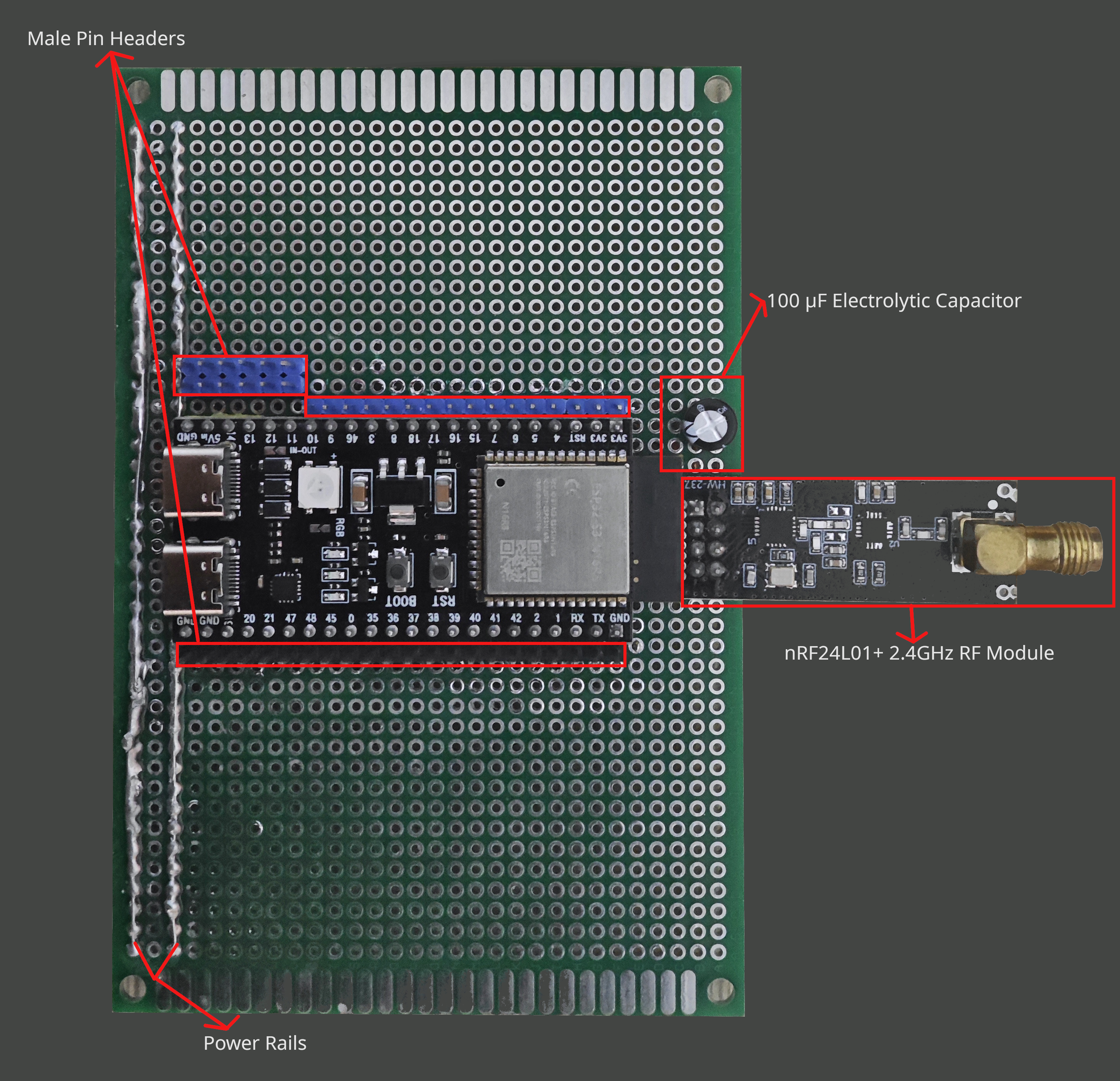
Figure 1: 6×9 cm Perfboard Controller Prototype (Top View) — ESP32-S3-N16R8 module, nRF24L01+ 2.4 GHz transceiver, 100 µF burst-smoothing capacitor, peripheral male header bus, and power rail headers.
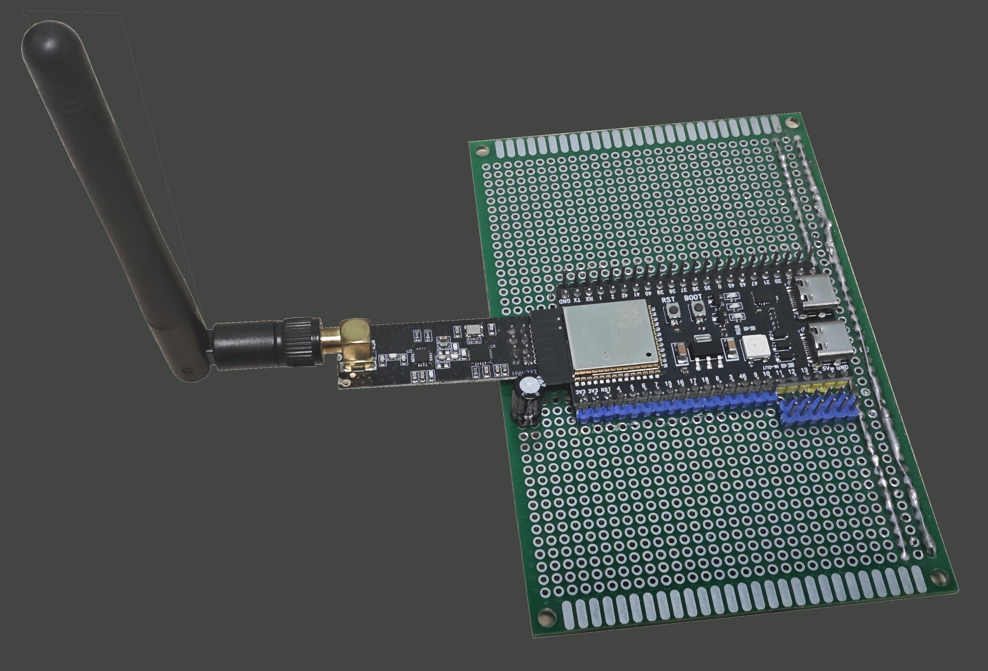
Figure 2: Side Profile — External 2.4 GHz SMA dipole antenna connected to the nRF24L01+ transceiver and dual USB-C ports (Native USB-OTG & UART).
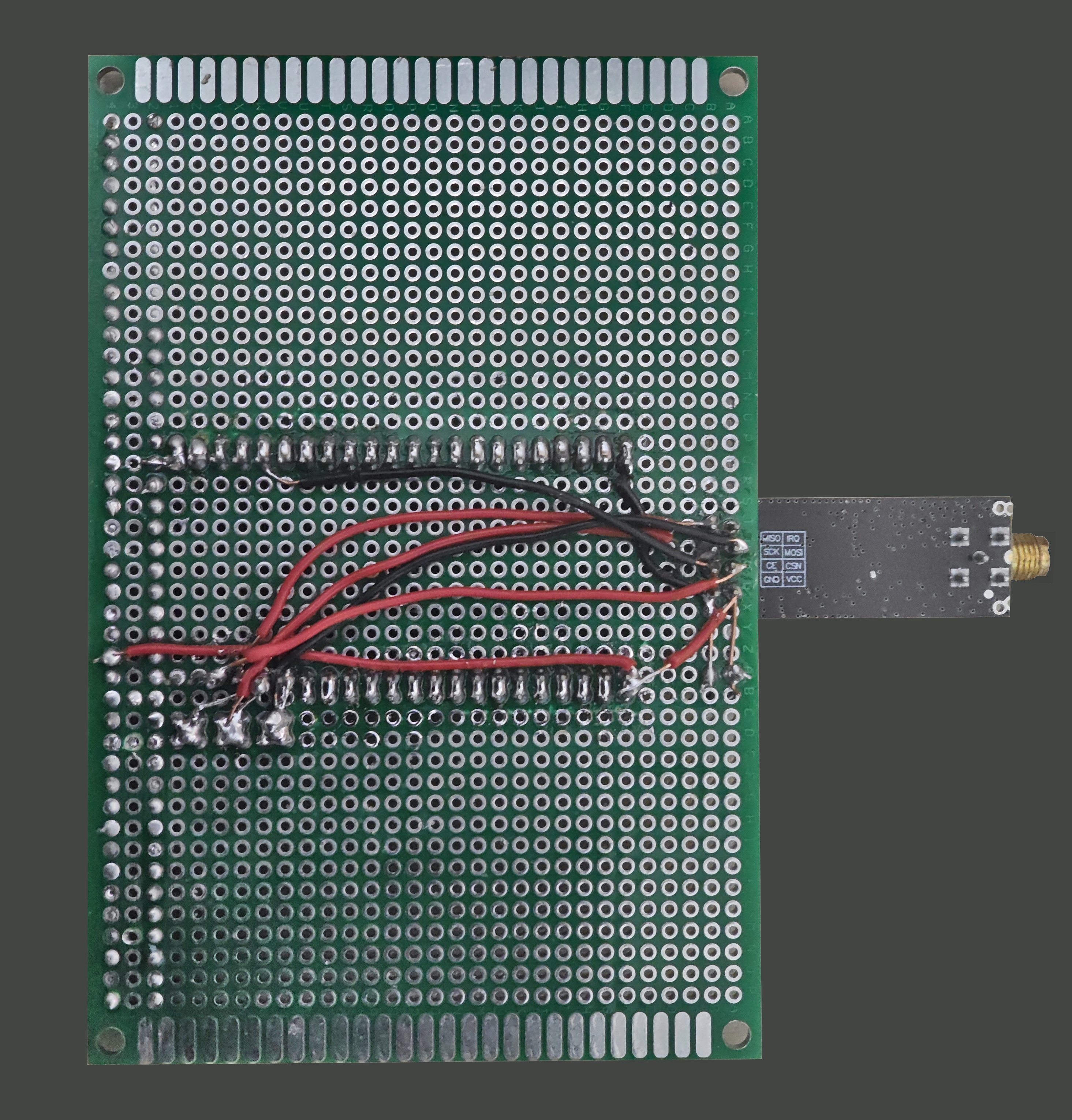
Figure 3: Underbody Bus Routing — Point-to-point solder bridges, common ground/power rails, and shared SPI2 signal routing on the 6×9 cm perfboard.
3. Hardware Architecture & Bill of Materials (BOM)
3.1 Handheld Controller (MFC — Transmitter Node)
| Subsystem | Component | Technical Details & Role |
|---|---|---|
| MCU | Espressif ESP32-S3-N16R8 | Dual-core Xtensa® LX7 @ 240 MHz, 16 MB Quad SPI Flash, 8 MB Octal PSRAM. |
| RF Telemetry | Nordic nRF24L01+ Module | 2.4 GHz ISM band transceiver over shared SPI2_HOST. |
| Display | 1.8" ST7789 TFT Color LCD | 3.3V logic, full-color SPI display with dedicated CS pin (replacing 7-pin CS-less 1.3" OLED). |
| Joysticks | 2× K-Silver (KS) PS5 Hall-Effect Modules | 3.3V active magnetic contactless gimbals for zero stick drift. |
| UI Input | KY-040 Rotary Encoder | Quadrature encoder (CLK, DT, SW) decoded in hardware via ESP32-S3 PCNT. |
| Voice AI | MAX4466 Electret Microphone Module | Analog pre-amplifier with adjustable gain for cloud-connected AI voice assistant input. |
| Data Logging | Arduino Micro SD Card Module | SPI interface, formatted FAT32 for local telemetry and configuration logging. |
| Audio Output | 1× Passive Buzzer + 2× Active Buzzers | Passive buzzer for melodies + 2× active buzzers for percussive UI clicks, driven by 2N2222 NPN Transistors. |
| Power System | Dual 18650 Li-ion + TP4056 + MT3608 | Dual 18650 cells, TP4056 charger, MT3608 DC-DC boost converter (5V rail), 100 µF electrolytic capacitor (nRF24 burst smoothing), and 100 nF ceramic decoupling caps. |
3.2 RC Vehicle (Receiver Node)
| Subsystem | Component | Technical Details & Role |
|---|---|---|
| MCU | GD32F103C8T6 Mini Board | 32-bit ARM® Cortex®-M3 real-time vehicle controller. |
| RF Telemetry | nRF24L01+ PA+LNA Module | High-power 2.4 GHz transceiver with Power Amplifier, Low-Noise Amplifier, and external SMA antenna (~1 km range). |
| IMU / Navigation | MPU9250 9-DOF Sensor | 3-axis Gyroscope, 3-axis Accelerometer, and 3-axis Magnetometer (I2C) for tilt-compensated heading. |
| Drivetrain | 4× JGB37-520 12V 333 RPM Gear Motors | High-torque 12V DC gear motors with built-in quadrature encoders for closed-loop PID velocity control. |
| Chassis / Box | DT-100 Project Box | Rigid black ABS enclosure (190 × 137 × 59 mm). |
| Power System | 12V Battery + Motor Drivers | 12V traction battery pack, heavy-duty H-bridge motor drivers, and 12–24V Waterproof Main Switch. |
4. Pinout Definitions (ESP32-S3 Controller)
The controller firmware (firmware/main/mmcontroller.c) and schematic (hardware/mfc-1.kicad_sch) allocate pins on the ESP32-S3-N16R8 as follows:
| Bus / Peripheral | Signal | ESP32-S3 Pin | Interface / Mode | Notes |
|---|---|---|---|---|
SPI Hub (SPI2_HOST) |
MOSI |
GPIO 11 |
SPI Master Output | Shared data line (nRF24L01+, Display SDA, MicroSD) |
SPI Hub (SPI2_HOST) |
MISO |
GPIO 13 |
SPI Master Input | Shared data input (nRF24L01+, MicroSD) |
SPI Hub (SPI2_HOST) |
SCK |
GPIO 12 |
SPI Master Clock | Shared clock line (nRF24L01+, Display CLK, MicroSD) |
| nRF24L01+ Radio | CSN |
GPIO 14 |
SPI Chip Select | Dedicated radio bus enable |
| nRF24L01+ Radio | CE |
GPIO 21 |
Digital Output | Radio TX/RX power state activation |
| TFT Display (1.8" ST7789) | CS |
GPIO 10 |
SPI Chip Select | Dedicated display bus enable |
| TFT Display (1.8" ST7789) | DC |
GPIO 9 |
Digital Output | Command vs. frame data selection |
| TFT Display (1.8" ST7789) | RES |
GPIO 8 |
Digital Output | Hardware display reset (BLK tied to 3.3V) |
| KY-040 Rotary Encoder | CLK |
GPIO 15 |
Hardware PCNT |
Quadrature channel A (1000 ns glitch filter) |
| KY-040 Rotary Encoder | DT |
GPIO 16 |
Hardware PCNT |
Quadrature channel B (direction sensing) |
| KY-040 Rotary Encoder | SW |
GPIO 17 |
Input (PULLUP) |
Push-button switch (300 ms software debounce) |
| K-Silver Hall Joystick 1 | VRx |
GPIO 4 |
ADC1_CH3 (12 dB) |
Analog X-axis (0–3.3V active Hall sensor) |
| K-Silver Hall Joystick 1 | VRy |
GPIO 5 |
ADC1_CH4 (12 dB) |
Analog Y-axis (0–3.3V active Hall sensor; 2nd joystick pending) |
5. Hardware Safety & Engineering Rules
- Enclosure Machining RPM Rule: Do NOT use standard fixed
16,000 RPMrotary tools on theDT-100ABS plastic enclosure; high friction melts ABS instead of cutting it. Machining is paused until the variable 3-speed rotary tool with2.35 mmdiamond cutting discs arrives. - Hall-Effect Gimbal Polarity Protection: Do NOT wire the K-Silver (KS) PS5 Hall-effect joystick
VCCbackward. Unlike passive potentiometers, these are active 3.3V CMOS magnetic sensors and will burn out immediately under reverse polarity. - 5V Sensor Level Shifting on GD32: Do NOT wire a 5V
HC-SR04ultrasonicECHOpin directly to the 3.3VGD32F103C8T6without a resistor voltage divider (or use the 3.3VVL53L0XI2C Time-of-Flight sensor instead). - nRF24L01+ Burst Decoupling: Always keep the
100 µFelectrolytic capacitor across thenRF24L01+VCC/GNDpins to prevent 3.3V rail brown-outs during PTX transmission bursts.
6. Immediate Next Steps & Engineering Roadmap
- 1.8" ST7789 TFT Migration: Rewrite the display initialization and frame buffer logic using ESP-IDF's
esp_lcdcomponent to replace the custom 5×8 monochrome OLED driver. - MicroSD Card SPI & FATFS Setup: Configure the Arduino MicroSD card module on the SPI bus and initialize the
FATFSvirtual filesystem (VFS) for reading/writing telemetry logs. - NVS Hall-Effect Joystick Calibration: Write the calibration routine for the K-Silver PS5 Hall-effect joysticks—measuring resting center, minimum, and maximum voltages and saving them persistently to ESP32-S3 Non-Volatile Storage (
NVS) flash. - GD32F103C8T6 Vehicle Receiver Firmware: Structure the ARM Cortex-M3 C codebase to poll the
nRF24L01+ PA+LNAmodule, readMPU92509-DOF I2C telemetry, and run closed-loop PID motor control on the 4×JGB37-520encoder motors.
7. Repository Structure & Build Instructions
multi-functional-controller/
├── docs/
│   └── PROJECT_HANDOFF.md           # Canonical engineering handoff & specification
├── firmware/                        # ESP-IDF v5.x C99 Firmware Project (ESP32-S3)
│   ├── CMakeLists.txt               # Top-level CMake project configuration
│   ├── sdkconfig                    # Verified ESP32-S3 target configuration
│   └── main/
│       ├── CMakeLists.txt           # Component registration
│       └── mmcontroller.c           # Master firmware: Shared SPI2, PCNT menu UI, nRF24 tuning
├── hardware/                        # KiCad 10 Electronic Design Automation (EDA)
│   ├── mfc-1.kicad_pro              # KiCad project file
│   ├── mfc-1.kicad_sch              # Controller schematic design (ESP32-S3, nRF24L01+, 100uF cap)
│   └── mfc-1.kicad_pcb              # Board layout & routing rules
├── images/                          # High-resolution 6x9cm perfboard prototype photography
│   ├── TOP_VIEW.png                 # Front carrier board overview
│   ├── SIDE_VIEW_WITH_ANTENNA.png   # RF antenna and profile perspective
│   └── BOTTOM_VIEW.png              # Perfboard underside solder bus wiring
├── .gitignore                       # Clean repository filter (builds, caches, local configs)
├── LICENSE                          # MIT License
└── README.md                        # Master engineering documentation
Build & Flash (ESP32-S3 Controller)
. $HOME/esp/esp-idf/export.sh
cd firmware
idf.py set-target esp32s3
idf.py build
idf.py -p /dev/ttyACM0 flash monitor
Author & Project Links
- Author: Ertunç Özbay
- Personal Workshop & Portfolio: ertuncozbay.dev
- Project Detail Page: ertuncozbay.dev/projects/multi-functional-controller.html
- License: MIT License